Circuit description
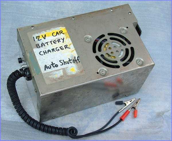
GENERALBeing someone who claim to know a little about electronics, friends and relatives would sometimes ask for a battery charger to help them charge up exhaused batteries. How can you provide a charger so that anyone one can use? The idea of this project came up in response to the above. To use the charger, the battery must not be totally dead, and the user must connect up both crocodile clips to the correct battery terminals before the charger can be started. Shorting the charger output terminals or connected them wrongly to the battery would not harm both the charger or the battery.
The instruction to use the charger is simple. Connect up the clips to the battery so that the red led on the charger is flashing, then press the start button. The charger will cut off once charging is complete. Simple, yes. This project is actually the combined effort of two designs, that's why there are two schematics: |
 |
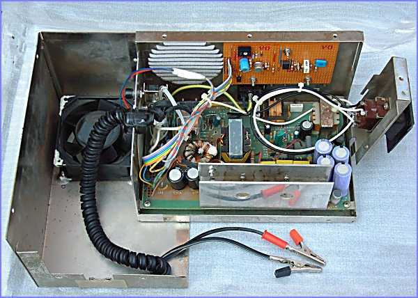
SWITCHING POWER SUPPLY SECTIONThe image on the right shows the modified supply and the additional charing control board mounted vertically at the rear. This is a power supply from the PC-XT era and was left unused for years. I am glad it finally had got some use afterall. The complete circuit of the supply is shown in the top schmatic. In order to modify a PC switching supply, you best bet would be to try to make sense of the complete circuit of the supply. Then you decide on which component(s) one should modify to make the power supply perform to one's requirement. In this project, only one voltage is needed so the components like rectifiers and capacitors for other voltages were de-soldered from the power supply. The original 5V supply winding was found to be three turns so I would need 9 turns for 15V output. After this turns increase, several components value need also be changed so as to trick the TL494 switcher IC into thinking 5V is at the output instead of 15V. |
 |
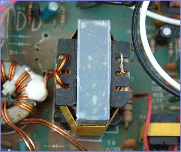
MODIFYING THE HV TRANSFORMERThe whole HV transformer was removed from the circuit board and dismantled. This is easily said than done because the HV transformer is resin dipped or stuck together by epoxy making dismantling very difficult. I have to heat the ferrite core carefully with heat gun to soften the resin and eventually separate the winding coils from the core halves. I performed this step carefully so as not to lose the spacers in between the cores. The spacer is vital as it sets the correct air gap between the cores and thus determines the inductance of the windings. Changing the inductance would most certainly make your power supply operate incorrectly. The second step is to carefully note down the winding arrangement and electromagnetic shields between windings as I need to restore them after winding modification. For the winding modification, if you can get multi-strand enamal wire so much the better but I made do with a solid wire instead which is really a bad practice I must say. Finally, the windings and cores were fitted together and insulation tested the transformer using 1000V insulation tester. As all is well, the transformer was soldered back into circuit and other components changed as in the schematic. After confirming the supply is working as it should and load tested to 10A, the charger control circuit can be built. |
 |
CHARGING CONTROL SECTIONThe second schematic details the circuit for the chager control board. It consists of the following three main parts: When the user connects up the output crocodile clips correctly to a discharged 12V battery(which should still giving out 8-12V at battery terminals), the red LED flashes to indicate all is well. Note: This requirement of 8-12V voltage from the discharged battery proves to be essential for the unit NOT to charge a dead or defective battery which gives much lower voltages or does not even have remaining energy to power up a relay. When an user reported back to me that the unit would not start but the LED is flashing, ten times out of ten the battery was proved to be defective. There is no point in charging a defective battery. After the unit is connected up correctly, user can then press the start button which energises a relay using the remaining energy in the battery. Once the relay is energised, it powers up the main switching power supply and charging current will then flows towards the battery.
|
 |