Circuit description
|
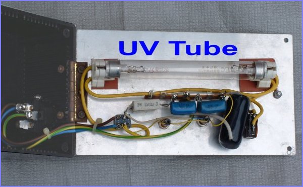
I built this eraser from easily obtainable parts. The main component being the UV tube and this should be a tube of clear glass where you can see the filament at each end of the tube. This perhaps is the difficult component to obtain now as more people are using Flash ICs instead of EPROMs. The AC input is switched and connected to a current limiting chain consists of resistors and capacitors. I have used several capacitors in parallel as I did have the required capacitance at the voltage of 300VAC or more. Two AC250V neon indicators allow the status of the unit to be seen without opening the lid. The unit is housed in a black plastic box with a hinged aluminum cover. When the cover is opened, eproms can be placed onto a conductive spronge pad at the bottom of the box, which enable the eproms be located directly under the UV tube when the cover is closed. The power is then switched ON and one neon indicator will light up. Usually, this will be the "Lamp OFF" indicator which is connected across the UV tube. When the UV tube has not striked yet, it appears like an open-circuit and all the AC240V will appear across it. When the start push button is pressed momentarily, a current is made to flow through the UV tube filaments and heat up the filaments. This in turn enable the tube to strike at the peak AC voltage and once it has striked, the current through the tube is sufficient to heat up the filament and keep the tube from extinguishing. The voltage across the UV tube then drops to tens of volts after striking and nearly all AC input voltage now appears across the resistor and capacitor current limiting chain. This lights up the other "Lamp ON" neon indicator while the "Lamp OFF" neon indicator goes off. By connecting the unit to an external mechanical timer for the AC supply, the unit is switched off after 20 minutes. This will provide a much longer life for the UV tube. |
 |