|
ICD2 is the In-Circuit Debugger designed and sold by Microchip to enable user to debug a PIC while an user program is running. It can also be used as a hardware programmer to send the HEX code into the PIC. Because Microchip is behind this product, therefore the product would be updated to enable it to work with all new types of PICs and in a word the ICD2 would never be outdated. It works on PCs with either the serial port or the USB port. New firmware will be downloaded into the ICD2 automatically should user select a PIC which cannot be handled by the existing firmware.
However, there is one problem, it carries a US$280 price tag. Then for some unknown reason, the bootloader firmware HEX file BL010101.HEX was included with a previous version of MPLAB and this enable people to try to clone the ICD2, using the firmware as a bootloader. One of the success stories is L.Stolz who published his design on the WWW. Since then, there are many similar designs came up and ICD2 Clones are being sold in EBay all around the world. |
GENERALThis ICD2 project is based on the concept of the L.Stolz design. After looking through several other ICD2 clone design, I changed the section that interfaces with the target PIC to0 suit my need. TTL buffers were use instead of direct input/output. This can be seen from the circuit diagram. I have used a 16F877-20/IP instead of the 16F876-20/SP commonly uses by all others simply because the 16F876 is far more expensive than the 16F877 which I can obtained from the same store. I did a very throughout research on which PIC is suitable for use and noticed that in the Net a "special" A version bootloader HEX firmware is available for the 16F876A and the 16F877A. Being not from Microchip origin, I decided not to use it but use the 16F877 instead. |
INPUT/POWER SECTIONSStandard RS232 to TTL interface is provided by the LT1081 IC which the same as MAX232 ICs. A hardware reset line is created such that the serial signal line DTR can reset the 16F877. The firmware BL010101.HEX for the 16F877 is downloaded via my first serial programmer. The two 7805 and 7808 combined to generate stable +13V and +5V for ICD2 itself and external PIC. I have choose to use 78 series instead of the 78L series simply because I have them around. |
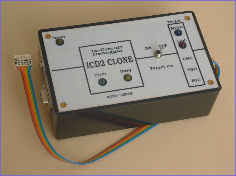
OUTPUT SECTIONI have decided to use TTL input and output buffers to drive the external PIC. Also I have redesigned the MCLR/VPP signal line to be more to my taste and added a switching for the Vdd also. |
INDICATOR SECTIONI like to know that the ICD2 is working so I have added the two original LEDs to indicate "BUSY" and "ERROR" condition. Moreover, I also added the MCLR/VPP LED and the Vdd LED and a four-pole toggle switch to isolate the external PIC if necessary. All the voltage sensing potentiometers are not connected to the PIC pins and the voltages were adjust to within 5% of the required values before these were connected. As it can be seen in the schmetic, setting the wiper to an extreme position can easily damage the PIC. Using a variable resistor this way would gives a more stable voltage divider than adding more resistors to prevent the possible damage. |
TESTINGThe whole circuit works first time power ON and MPLAB detected it right away. It then automatically downloaded the required firmware for 18F4455 and subsequently found the 18F4455 as its target. If you are trying to one for yourself, I would recommend to look over several schematic design and choose one that you can understand how it works. In that case you can clear any bugs and set it up without problem. There are lot of cases that people failed to make a working ICD2 and ended up buying one ready made. |