GENERAL
This circuit is the result of a reply to a posting on a DIY Electronic board where one user asked how to use an opto-isolator to measure input voltage of 0-10V. After posting of my reply, I built the circuit on a breadboard and tested the response of the circuit.
HOW IT WORKS
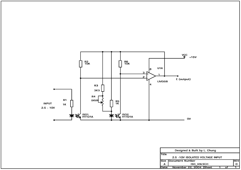
A voltage between 2.5V to 10.0V is applied to the LED of the first optoisolator via a 1K resistor. This produces a current and is reflected to the output of the optoisolator collector load resistor. By connecting up a similar setup of LED on the output side, the optoisolator supply voltage is then varies such that the voltages on two collector loading resistors are equal. Thus effectively we created a "mirrored" voltage of the input voltage. We can fed the voltages of the two collector loading to the inputs of an LM358 opamp and it will alter it output to bring the two voltages into balance. Note that R3 and R4 were not fitted for the first trial.
The test results in the first trial was close enough for rough measurement purposes. By adjusting the current of one of the LEDs using a variable resistor R4 and R3, the performance of the circuit (third column of results) is much improved. By applying 9.95V to the input, the VR4 is adjusted until the opamp outputs exactly 9.95V. The second set of resutls were then taken.
However, please be aware that there are long term drift problems to this type of setup so the perfer method is to pick and match two optoisolator which have very similar characteristics and use as small a LED drive current as practicable.
TEST RESULTS
| Input volt X (V) | Output Volt E (V) | After Adj. E (V) |
| 9.95 | 10.1 | 9.95 |
| 9.50 | 9.66 | 9.50 |
| 8.00 | 8.13 | 8.00 |
| 7.00 | 7.10 | 7.00 |
| 6.00 | 6.09 | 6.01 |
| 5.00 | 5.06 | 5.00 |
| 4.00 | 4.04 | 4.00 |
| 3.00 | 3.03 | 3.00 |
| 2.50 | 2.52 | 2.50 |
| 2.00 | 1.40 | 1.38 |
You can see that the circuit failed with input voltage below 2.5V. This is as expected because the LED would not conduct with less than 2.0V.
POSSIBLE SOLUTION FOR 0V INPUT
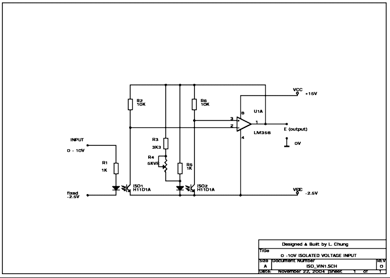
It is possible to measure zero volt input if the device (e.g. a PSU) being measured can also provide a -2.5V voltage. In this case, the cathode of the input LED can return to this -2.5V rail and the LED current is maintained even with 0V input.
However, the same arrangement must be applied on the opamp side. i.e. the cathode of the second LED, emitters of both optoisolators and the opamp supply pin 4 must also be tied to a separate -2.5V rail in order for the circuit to work. See the circuit below:
