Circuit description
|
You will need to download the PDF or GIF and print the circuit out in order to read the components clearly and to follow the discussion of the rest of this webpage.
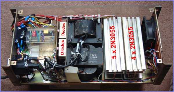
GENERALThis project is about a 13.8V 16A linear voltage regulator that I designed and built for my radio transmitter. The actual building of power supply with output more than a few amperes gets complicated because there are voltage drops on the connecting wires. This is what the circuit diagram cannot tell you. Great care must be taken in order that the power supply performs as designed. The component parts used were from previous surplus equipment. The performance of this power supply is the best I have ever built. Many published voltage regulator circuits would use three or four 2N3055s for 15A output but the beta of 2N3055 drops when collector current IC is high so keeping to 2A per transistor works best for me. For reference purposes, the 30V 5A regulator by Farnell use eight 2N3055s for just 5A current output. You may try to use less transistors but then again the thermal stress on each would be higher. At the end, you have to balance money with performance and reliability. |
 |
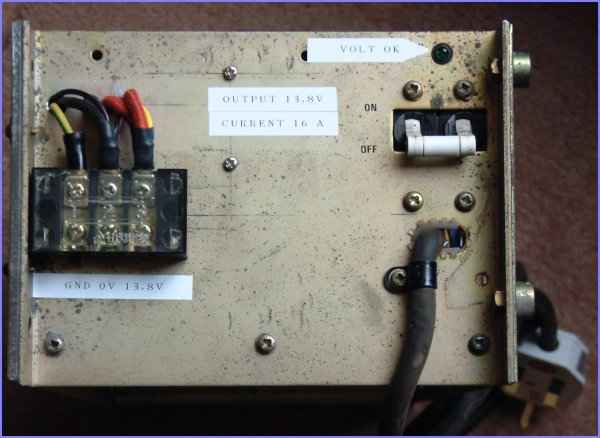
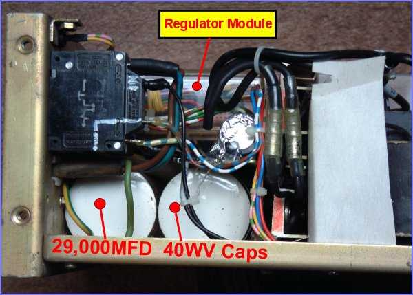
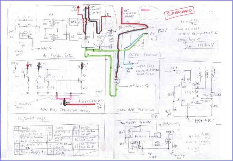
INPUT/OUTPUT SECTIONAC240V is switched via a magnetic circuit breaker(MCB) at the top right hand corner of the photo and routed to two identical 115V/10V 15A transformers with primary windings connected in series. These two transformers were recovered from surplus stocks. On the MCB there are two terminals for shunt tripping. This is an internal coil which opens the MCB and disconnected the AC source if 12V is applied. The energy source of the tripping supply is stored in a 4,700uF capacitor(C50) and will maintain the trip circuit current for a short time even after the main crowbar SCR has fired. In the photo you can also see a "Volt OK" LED just above the MCB. The volt OK LED operates off a simple voltage comparator and will light up if the output voltage is between 13V and 14.6V. The circuit of this part is not shown in the above schematic. The output terminal blocks is located at the left. You might discover there are at least three wires connected to both the positive and negative terminals. You would wonder why this is so? It turns out that connection like this is essential for the proper operation of the power supply when the output current is higher than a few amperes. This is the only way that the regulator can compensate for connection wire voltage drops. |
 |
RECTIFY / SMOOTHING SECTIONThick size wires are respresented in the schematic using thick lines. This is what normal schematics do not show you. The correct usage of thick wire where needed is the key element in the overall performance of the regulator. The secondaries of the transformers are also connected in series to give 20V RMS feeding into two bridge rectifiers connected effectively in parallel. The eight bridge rectifier diodes are mounted on heatsinks and the output of each bridge rectifier connects to one 29,000uF 40V smoothing capacitor. The two positive capacitor terminals are interconnected using a longer than necessary heavy guage wire. Each capacitor then acts as the source of current for four 2N3055s, which have current balancing resistors at their emitters. Using this arrangement, roughly half the load current will flow through one bridge rectifier.
|
 |
HIGH CURRENT PASS TRANSISTORS SECTIONIn order to pass 16A safely, a total of eight 2n3055s are used, being driven by another 2N3055 under the control of the familiar IC regulator uA723C. This makes up the total 2N3055s to be nine, mounted as 4 & 5 on a pair of heatsinks. Current balancing resistors are connected directly at the emitters of each 2N3055 to a pair of common tinned wires which joined together at one end of the current sensing shunt(0.041ohm). The current shunt was made using several thick resistance wires in parallel and the required length found out using DVM and a current source. The ends are then blazed to a brass terminal for easy connection of internal wires. |
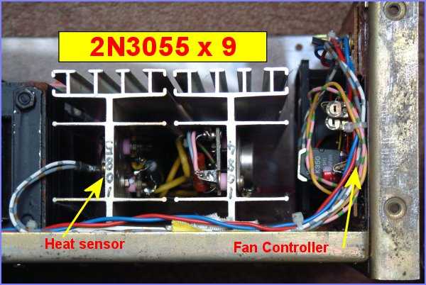 |
FAN CONTROL AND VOLT OK LED BOARDA temperature sensor mounted on the heatsink sense the heatsink temperature and activate normal cooling fan speed when it reaches 75 degree C. Fan is normally on low speed running at 5V to reduce noise. As the fan might not start reliably at 5V, full voltage is applied for several seconds to start the fan running normally. This is achieved via C91 and Q91 in the schematic. Also on this board is a comparator which light the "VOLT OK" LED on the panel should the output voltage is between 14.6V and 13.0V. When first switch on, the LED and the fan running on high speed indicate everything is well. |
 |
OUTPUT PROTECTION SECTIONWhen the voltage output of the regulator goes up for whatever reason, the overvoltage protection circuit in the voltage regulating section (discussed later) will issue a signal to fire the crowbar SCR. This effectively short circuited the output and prevent current flowing via external load. For crowbar protection to be effective, the SCR must be placed as near to the output terminals as possible and sufficient current carrying capacity is ensure by selecting a high current SCR of RMS current over 20A. I would like to use one with higher current rating but the one I used was already available and I do not wish to buy a new one. The firing of the output crowbar SCR also caused the undervoltage shutdown to operate and this will trip the input MCB, reducing the thermal loading to the SCR to a low level so no heatsinking of the crowbar SCR is needed. |
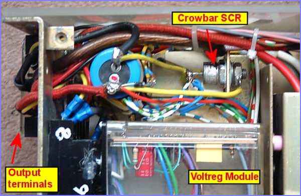 |
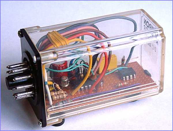
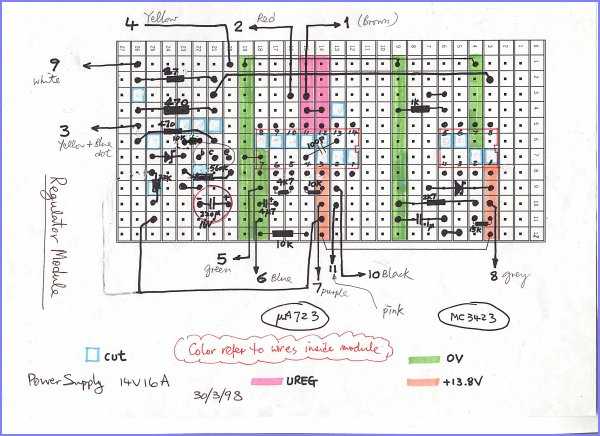
VOLTAGE REGULATOR SECTIONThe voltage regulator IC uA723C and the overvoltage sensing IC MC3423 were housed in a 11-pin case. This provide excellent dust proving of the circuit components as the cooling fan is continuously drawing dust into the supply casing. The 11-pin case is available from Malpin or RS Components althought you might not be able to get a transparent case like mine. My 11-pin case was salvage from a relay which I don't use anymore. The connection of the 11-pin case is made using a standard 11-pin relay socket mounted on the casing. Some important signals and connections are duplicated on surplus pins to make the whole unit more reliable and to cater for single failure of connection pin or wire. The extra pins are there without needing extra cost. |
 |
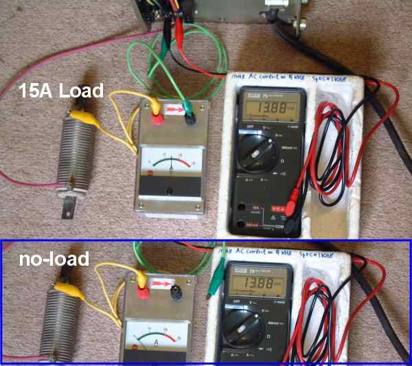
PERFORMANCE & TESINGWhen you finally built your power supply, nothing more satisfying than to actually power it up and see how it performs. You first takes the output no-load voltage reading, then connect up to a load via a 30A ammeter to the output while still monitoring its output voltage using a DVM. Why use a DVM? Because it will give you the actual voltage change when a load is applied. An analog meter will barely moves with a 0.1V difference but a DVM can show you changes as small as 0.01V. If you can see the changes with an analog multimeter, there is no need to use a DVM. Now, what would you expect from an amateur-built 15A power supply? Well the photo tells you that the power supply does not even care about 15A loading on its output, the voltage virtually remains unchange. This is, however, not actually possible. What you needs is more voltage resolutions on your DVM so that you can reads down to mV changes. Get a 5-1/2 digital meter which can be more expensive than your supply or alternatively try connecting the negative terminal of a 12V battery to the negative of the power supply, and the DVM between the supply positive and the battery positive terminal. You have effectively subtracted 12V from the power supply output voltage, as measure by the DVM. Now you can select the 2.000V range on the DVM and reveal how your power supply performs under load. I did and the voltage drops 3mV between no-load and 15A full load. I think you would agree that this is quite satisfactory for a simple power supply using the very common uA723C IC. |
 |
AFTER THOUGHTSBuilding a high current regulated power supply is not an easy job. The difficulties lies in careful planning and circuit design, the use of suitable wiring material and the recognition of voltage drops on the current carrying conductors. I have reached the end of this project. If you also wants to take the challange of building a high current regulated power supply, I would suggest you first made up a detailed plan of how the various wirings run and their size. I did and I can now show you some detailed drawings I made during the design stage. At the time when I built the unit, it was not intended to be shown to others on the web. Now I have access to webpages well I think these knowledges can be shared and if I can help one in a million, I'll be happy. |
 |
 |