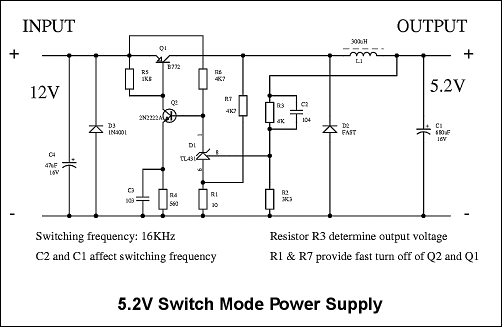
Circuit description
|
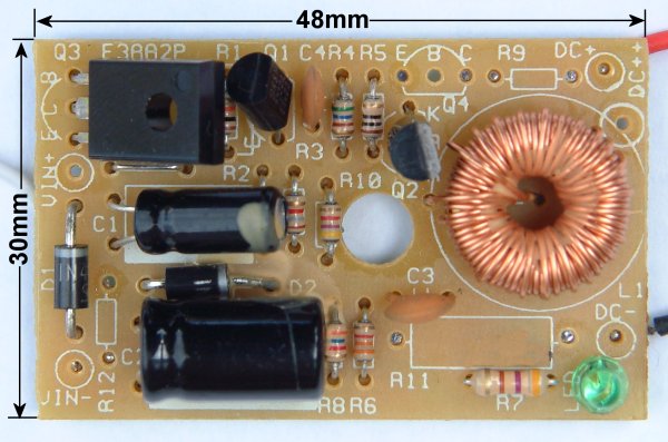
Note: The component designation in schematic diagram is automatically assigned by the Schematic Capture program and is not amended to follow the actual circuit board photo. All reference to component is based on the schematic diagram. This small circuit is from a mobile phone adaptor. As from the dimensions the size of the circuit board is very small. On the right hand lower corner is a green LED and series resistor I added after the schematic is drawn. An interesting point to note is the ten ohm resistor R1. If this resistor is bypassed and TL431 pin 6 connected to 0V, the output voltage is virtual contant at 5.15V with a loading of 22-Ohm when input voltage varies between 8V to 16V. With the resistor R1 in circuit, there is a 0.1V rise in output voltage between the same input voltage range. However, the supply current increased 20mA from 120mA to 140mA as the transistor Q1 is turned off slower. All the components are cool with a 0.5A output loading. The output filtering capacitor affect the switching frequency because TL431 depends on the output ripple for correct operation. In this case, too large a capacitance value might not give a good performance as the switching frequency is too low. If capacitor C2 is removed, the circuit might operate in linear mode but I have not done the check. |
 |