Circuit description
|
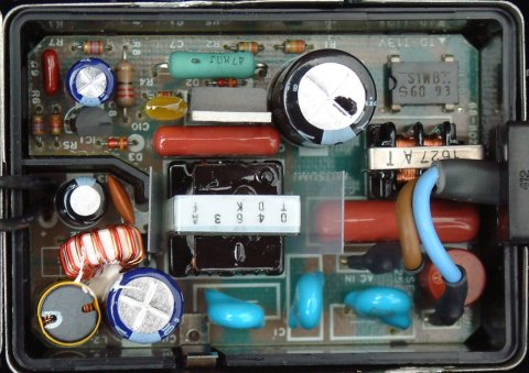
Note: The component designation in schematic diagram is automatically assigned by the Schematic Capture program and is not amended to follow the actual circuit board photo. All reference to component is based on the schematic diagram. The whole circuit is enclosed in a two-part metal box soldered at the seams. This has to be broken in order to reveal the internal components. This switching supply circuit is a bit different from the normal switching circuits in that no optical feedback of the output voltage is used. Instead, signal from a separate winding on the transformer core provides the feedback. This feedback voltage is rectified by D5 and provide the anode voltage of TL431. When the voltage across R4(3K3) exceed 2.5V, TL431 conducts and shunt the base drive of Q1. The regulation of this circuit is rather poor as can be seen in the loading graph. Either this is done on purpose by the designer or there is much room for improvement. Interested reader can also download the LT1725f.pdf which is a specific IC from Linear Technology for this type of feedback application at this link. |
 |