Circuit description
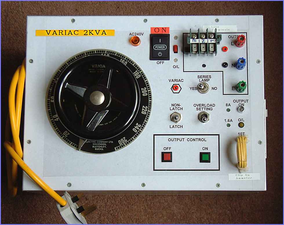
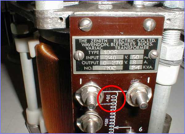
GENERALVariac(A tradename), short for variable AC transformer, is an invaluable tool in testing all projects which require AC power supply and is best for testing transformers, current transformers and powering up appliances after repair. This project explains how on/off switching and protection can be added to make the variac more versatile in daily use. The variac was bought from eBay as new one is quite expensive and very few shops in UK are selling them. Zenith brand variac were well known for their construction quality but other brands are also fine if you can get hold of them. One tapping point on this variac is rated at 30V AC and can be rectified for use by the control circuit. If the variac you have bought does not have such a tapping, you can add a small transformer instead. All depends on what type of relays you have already got. I have got an old 24V high current relay so I can use the 30V tapping. The rectified voltage peak to 40V and is directly applied to the 24V relay coil via the ON switch. When the relay operates, an economising resistor is inserted in its coil to hold the relay in the energised position at a reduced voltage of about 15V. Thus the relay is energised with 40V and then hold with 15V. You will have to experiment with the relay to find out the best resistor to hold the relay under reduced coil voltage. The start/stop circuit is pretty much very standard circuit design with the addition of the latch and unlatch toggle switch. This switch enable the output to be available only when the start push button is depressed and switch off when it is released. |
 |
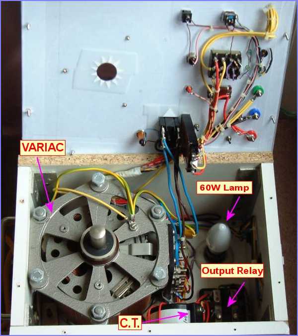
PROTECTION SECTIONThe overload selector switch doubles as an output ON/OFF switch and output is disconnected when it is in the middle position. This is a 15A 250V AC rated 4PDT three position switch with center-off arrangement and is difficult to obtain. There are three protection ranges for the output circuit. The first is a series connected 60W filament lamp which limit the current to about 150mA. Current in excess of this would cause the lamp to light up. A switch is fitted to bypass this lamp if required. The next range operates at 1.6A via an overload relay. Basically this is a bi-metallic device and operates when the bi-metal is heated up by the passing current. When this overload relay operates, the supply to the output relay is interrupted and an orange LED light up to signal the overload condition. Using a current transformer(CT) of 200A/5A rating and eight turns of wire through the center of the transformer, the CT ratio is reduced to 25A/5A and 8A current in the primary wire would translate to 1.6A secondary current. This current is connected to the same overload via a selector switch. As far as the overload relay is concerned, it senses 1.6A current is flowing when the actual current in the primary is 8A. However, it is much cheaper to change the circuit to use an additional 8A overload relay instead. A neat feature is the ten-turn wire loop in series with the load seen in yellow at the top right corner of the image at right. Basically this allow a clip-on ammeter to measure the current with 10-times the magnification. Most common clip-on ammeter have difficulties in measuring correctly a few amperes and this 10-turn loop provides a nice solution with ease. |
 |