Basically this is a modified design based on the original circuit and idea from the following website:
See the original schematic here
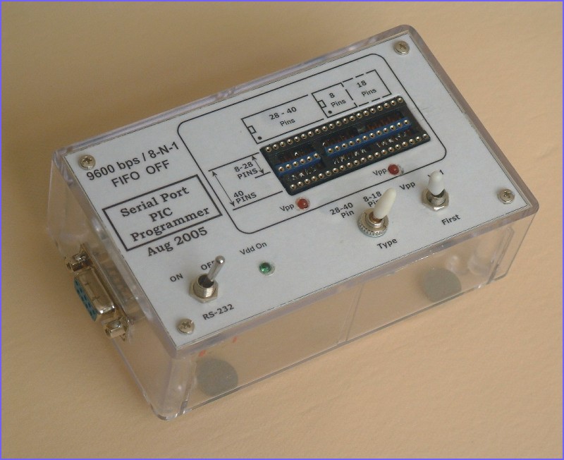
Description: Multi PIC Programmer 5 Ver.2
1. The circuit has been redrawn to aid my understanding of how it works.
2. A Vpp/Vdd toggle switch is added as I have found too many people complainted that some PICs failed to be reprogrammed after programmed once because of Vpp/Vdd first up sequence requirement. Some PICs requires Vdd first while others requires Vpp to be applied first.
3. A 1K resistor is added to the Vpp/MCLR line so that a wrong selection of PIC types would no longer damaged a PIC by applying 13V to non-MCLR PIC pin. However, this is not confirmed and tested.
4. Pin 18 of the socket connection to 0V has been removed as this caused my 18F4455 failed to program.
5. Three LEDs added to let me know about the status of the programmer. The first one is Vdd, which lights when +5V is supplied to the PIC. Then two Vpp LEDs with either one short-circuited depending on the PIC selector switch. These two LEDs are placed close to the associate socket pin to indicate where the Vpp is being applied. This helped me in trouble shooting the programmer without a PIC in the socket.
6. A four-pole toggle switch added to switch off the RS232 signals and power down the programmer.
This is the first programmer I have built. I did read a lot of the material on the Net regarding how unreliable the JDM design is. Therefore the first thing I did is to build the voltage section on the breadboard. Hooked it up to the serial port and measured voltages on capacitors C1 and C2 to confirm that it can actually reachs +5V and +13V. After the test was sucessful, I then proceed to complete the whole project. It enabled me to program a 16F877 which I later use to build my second PIC programmer & debugger, the ICD2 Clone on other part of this website.
The programming software used is WinPic, available here. DL4YHF's WinPic Programmer installation
The setting of WinPic is shown in the image. Make sure the selection is correct. The Multi_Pic_5V2.ini file is available here.
I can recommend this design to anyone wishing to build his/her first programmer, but only after confirming the following points:
The PC serial port output voltage is extremely important for this design to work because the programmer get all its power from the serial port. One do not need another power supply and this is the main attraction of this JDM design to hobbyist. Unfortunately only those serial ports on older desktop PC is likely to give more than +/-7.8V between pin5 and other pins when measured using a meter. To confirm the serial port on your PC, places black meter lead on serial port pin5 and measure voltage on other port pins. If the measured voltage value on pins is less than 7.8V positive or negative, then do not try to build this design. It will not work properly.
serial port on laptops are most likely do not give sufficient voltage output for the design to work
USB to serial converter will definitely not work as I read from various sites.
Pin5 of the serial port is common ground to the PC but its not the Vss or 0V for PIC in this programmer. Therefore if one connects the signals out and try to do ICSP to external circuit board, the circuit board must be isolated with 0V not connected to 0V of the PC or else damages would occurs.
The first alternative to building this programmer is to build the parallel port programmer, which uses external power supply and usually works very well without any major issues. I have already built more than three so I can say for sure. You can see the one I built here.
If you would like to stick with using the serial port, another alternative is to search the NET for other designs which uses serial port but also allow the connection of external power supply to the programmer. Then the serial port pin voltage level does not become critical as in this self-powered design.