My parallel programmer and ICD2 Clone both have an 6-way output lead which I can use for PIC In-Circuit Serial Prpgramming(ICSP). When I am not using the ICSP feature, I want to be able to program PIC out of circuit using a ZIF socket. However, different PIC requires different connections for correct programming signals so it is a bit difficult to have an universal connection that requires no switching.
One method used by the P16PRO40 is to switch the VPP voltage using two semiconductor switches and this partly solved the problem. However, the ICD2 Clone is meant for ICSP and does not have this feature build in. The closest I saw is several pin headers(for different PICs) for user to selectively connect the ICSP cable. This is not a good method.
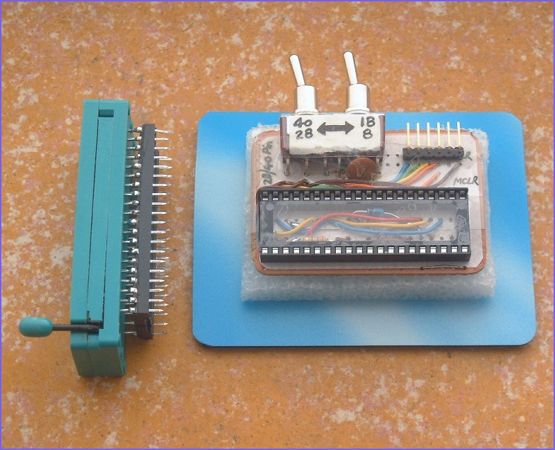
As a result I have designed a configuration to allow me to attach a ICSP cable and select the correct connection by flicking a switch. I do not have DPDT switch that is of the PCB mounted type so I use two SPDT switch instead. I just flick them together. If you are going to duplicate my socket connection, you can use a DPDT switch as shown in the schematic.
One pin on many modern PICs that causes concern is the PGM pin. This pin if left floating and not tied to Vss would cause programming error as the PIC might possibly enter Low Voltage Programming Mode after the configuration is erased to all "1"s in preparation for new code loading. I have taken care of this in the design too.
Two components that you might notice are the resistor and the zener diode. They serve an important function. It is easy NOT to remember to select the correct PIC type via the switch and without these two component, one would easily cause damage to the PIC by applying +13V to other PIC pins other than the MCLR pin. Should this happens, say when a 28/40 pin PIC is inserted and the switch is in the 8/18 position, the +13V MCLR voltage would be applied to the wrong pin and the PIC internal protection diode would conduct. However, the resistor in this case would then limit the diode current to a safe level while the zener diode would clamp the overall PIC VDD voltage to 5.6V to avoid damages. These tow components have little or no effect on normal programming.
The ZIF socket is an expensive component. Therefore I find it a bit wasteful to just soldered it up permanently to a board. My solution is to solder the ZIF socket to another IC socket shown above. Now this gives me flexibility in re-using the ZIF in all sort of other places like my serial programmer or a circuit board which normally takes a 40-PIN CPU like AT89C51. I just plug in the ZIF to the socket on the CPU PCB, insert my CPU for testing in the ZIF or remove it for another programming run until I am satisfied of the result. Then I insert the CPU directly back to the circuit board.